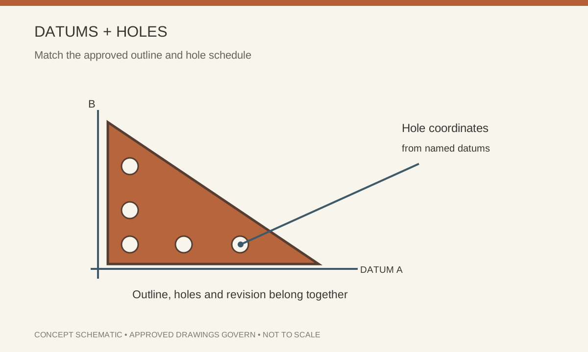
Begin with one controlled coordinate system
A gusset plate drawing should show how the outline and hole group are located from the same reference. Chained dimensions, an unexplained CAD origin and a separate hole schedule can describe different interpretations of a part that looks identical on screen. Ask the project team to resolve the governing dimensions before fabrication.
The procurement task is to transmit the accepted connection geometry. It is not to choose bolt spacing or hole size independently. Keep the engineer-approved hole type, edge-distance requirements and any slot direction together with the plate grade and thickness.
Distinguish hole geometry from hole-making method
Describe the finished hole first: circular or slotted, nominal size, coordinate and the applicable tolerance. Then ask the processor to confirm a route that meets the project requirements. A drawing that says only “laser cut” has not necessarily defined how a bolt will fit or how the hole will be inspected.
Show any machining allowance or finishing step explicitly. If the connection depends on a trial fit or inspection of a first part, identify the acceptance hold point and who releases the remaining quantity.
| Checkpoint | Information to agree |
|---|---|
| Outline and holes | Use named datums and a dimensioned or controlled coordinate schedule |
| Slots | Show long-axis direction and the approved hole type |
| Part identity | Keep mark, revision, grade and thickness together |
| Acceptance | Define dimensional records and any trial-fit requirement |
Do not merge handed or revised parts
A mirror image may have the same outside dimensions but a different installation orientation. Give left-hand and right-hand parts separate marks where the drawing requires them. A changed hole coordinate should trigger a controlled revision, not an informal instruction on an old cutting file.
When comparing quotations, check that each offer uses the same revision and includes the same hole, edge and identification scope. A lower price for unfinished blanks is not directly comparable with a price for inspected, ready-to-fit connection plates.
Before releasing the order
- Issue the drawing and CAD file with matching revisions.
- List quantities by part mark and hand.
- Identify finished holes, edges and any machining allowance.
- Agree inspection records and pack labels before dispatch.
Use a gusset plate schedule to compare identical fabrication scope. The final connection design and acceptance standard remain the project authority.
Review the related product inquiry with the approved drawing and material schedule.
AISC engineering FAQs: general fabrication ↗
General reference for the discussion; the applicable material standard, approved project design and purchase documents govern the order.