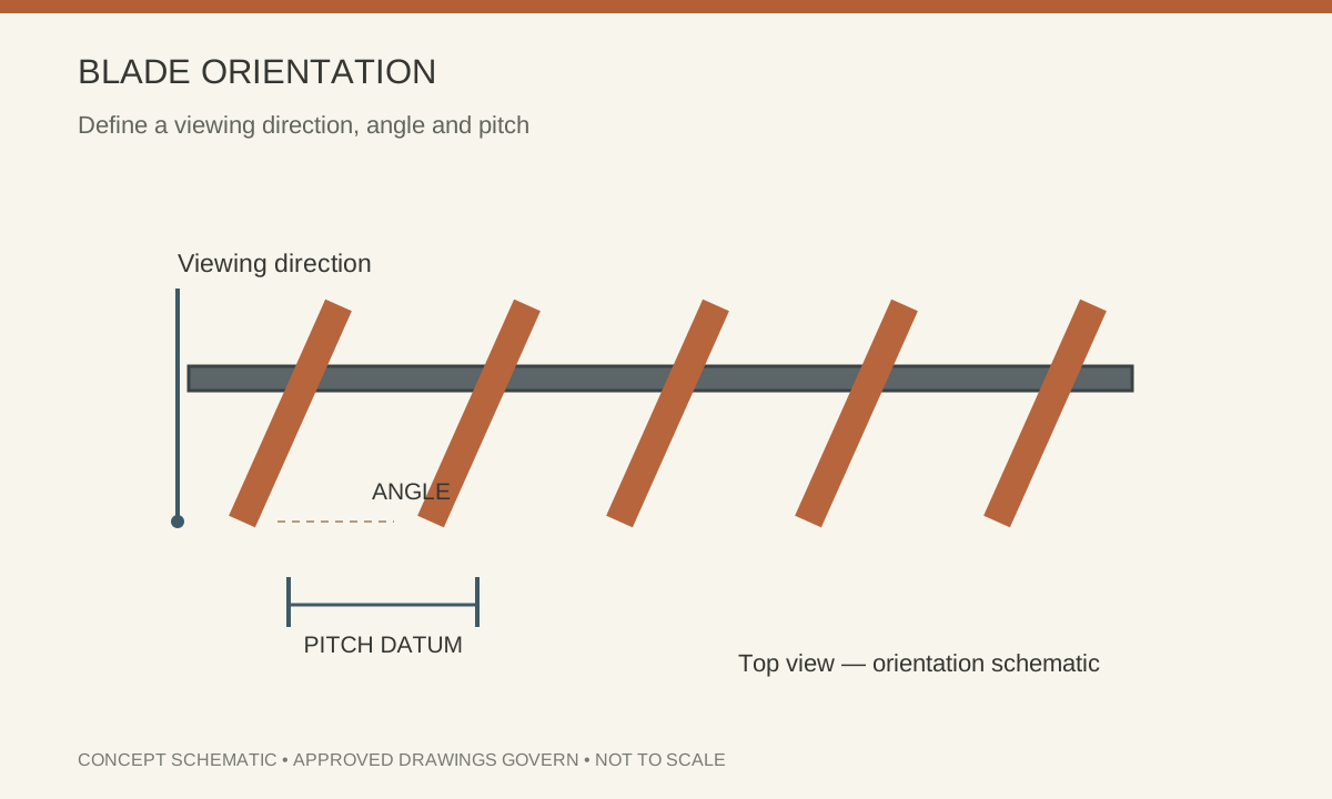
Give the angle a reference and viewing direction
An angle value alone is incomplete. Show the facade or frame datum, the direction from which the section is viewed and the position of the blade face. Where assemblies turn a corner, add sections for each orientation instead of assuming a single typical view covers every elevation.
State whether pitch is measured between centres, faces or another reference. Include the blade depth and profile so the apparent opening can be understood from the same drawing.
Schedule blades separately from their support frame
For each blade mark, list length, section, thickness, end cuts and connection details. Identify mirrored brackets or reversed end conditions. Then state whether frames, brackets, fasteners and anchors belong in the same quotation or are provided by another contractor.
A small sample assembly can reveal access and orientation issues that an isolated finish coupon cannot show. Define what the sample is intended to approve: appearance, fit, fixing access or a separate performance assessment.
| Checkpoint | Information to agree |
|---|---|
| Angle | Datum, viewing direction and blade face |
| Pitch | Measurement basis and repeated spacing |
| Handing | Mirrored pieces and different elevation orientations |
| Scope | Blades, frame, brackets, anchors and any required assessment |
Distinguish layout from system performance
Blade geometry affects the physical opening, but an opening dimension does not establish a ventilation, shading or weather-performance rating. The designer should specify the required assessment for the actual assembly if those functions are part of the brief.
Coordinate inspection access and paths for moisture to leave the blades and support pockets. Finish selection should include rear faces and nearby materials, not only the front elevation seen in a rendering.
Before releasing the order
- Issue elevation and section drawings together.
- Allocate unique marks to handed blades.
- Define visible faces and connection access.
- Specify any sample assembly and its approval purpose.
Use the blade schedule as the link between the architectural layout, the fabrication drawing and the installation sequence.
Review the related product inquiry with the approved drawing and material schedule.
SSAB recommendations for architects ↗
General reference for the discussion; the applicable material standard, approved project design and purchase documents govern the order.